
Set Neuron Parameters
This is an example of how to set neuron parameters, such as encoder and decoder matrices, on the FPGA. This is useful if you’ve pre-solved weights (encoders and decoders) elsewhere or if you want to start in a known state.
The FpgaPesEnsembleNetwork encapsulates a Nengo Ensemble and Connection object, each of which you can modify. Modifying the attributes of the Ensemble object alters the neuron parameters simulated on the FPGA, while modifying the attributes of the Connection object alters the parameters of the FPGA ensemble output connection that is simulated on the FPGA.
In order to change the attributes of the Ensemble or Connection objects, first create the FpgaPesEnsembleNetwork object:
fpga_ens = FpgaPesEnsembleNetwork(...)
From which you can access the encapsulated Ensemble and Connection objects (using the .ensemble and .connection attributes of the FpgaPesEnsembleNetwork object respectively):
fpga_ens.ensemble
fpga_ens.connection
Use these two objects to set specific attributes as desired. Please look at the Nengo documentation for Ensembles and Connections for a full list of options.
Step 1: Set up Python Imports
[1]:
%matplotlib inline
import matplotlib.pyplot as plt
import numpy as np

import nengo
from nengo.solvers import NoSolver

import nengo_fpga
from nengo_fpga.networks import FpgaPesEnsembleNetwork
Step 2: Choose an FPGA Device
Define the FPGA device on which the remote FpgaPesEnsembleNetwork will run. This name corresponds with the name in your fpga_config file. Recall that in the fpga_config file, device names are identified by the square brackets (e.g., [de1] or [pynq]). The names defined in your configuration file might differ from the example below. Here, the device de1 is being used.
[2]:
board = 'de1' # Change this to your desired device name
Step 3: Create Some Weights
Generally, the encoder and decoder matrices can be generated using your desired methods (e.g., through randomization, or by using a machine learning algorithm). Typically, the gain and bias values of the neurons need to also be configured to work with the pre-generated weight matrices in order to have a computationally functional model. In this notebook, Nengo will be used to generate the various neural ensemble parameters that functionally define a communication channel.
The example code below uses a 2-dimensional neural ensemble consisting of 4 ReLU rate-based neurons. The encoders for each neuron will be configured such that each neuron represents one quadrant of a sine and cosine period. To use Nengo to generate the various neuron parameters, two steps are required. First, a temporary (parameterization) network with the desired ensemble properties (e.g., number of neurons, firing rates, etc.) is created. Then a nengo.Simulator object is initialized using
this network and in doing so, Nengo computes the neuron parameters specific to the parameterization network. These parameters can then be retrieved using the nengo.Simulator object.
[3]:
# Dummy network to generate neuron params
with nengo.Network(seed=1) as param_net:
    # Ensemble with our desired parameters:
    a = nengo.Ensemble(
        n_neurons=4,  # Number of neurons
        dimensions=2,  # Dimensions
        neuron_type=nengo.RectifiedLinear(),  # Neuron model
        encoders=[[0.707, 0.707], [-0.707, 0.707],  # Encoders
                  [-0.707, -0.707], [0.707, -0.707]],
        intercepts=nengo.dists.Choice([0]),  # Intercepts
        max_rates=nengo.dists.Choice([100])  # Max rates
        )

    # An output connection is needed in order for Nengo to solve
    # for the decoders. Note that because no function is defined
    # for the output connection, Nengo will compute decoders that
    # approximate the identity function
    # (i.e., making a communication channel).
    b = nengo.Node(size_in=2)
    conn = nengo.Connection(a, b)

# Neuron parameters are generated when the simulator object is created.
with nengo.Simulator(param_net) as param_sim:
    bias = param_sim.data[a].bias
    encoders = param_sim.data[a].encoders
    gain = param_sim.data[a].gain
    decoders = param_sim.data[conn].weights
Step 4: Create the FPGA Ensemble
The network created in the previous step was used generate the neuron parameters and is not intended to be run on the FPGA. Here, the Nengo model that is to be run on the FPGA is created. Note that for this example, the decoders have been initialized to zero in order to demonstrate the effect of using a network with a decoder weight matrix of zero versus a network using the pre-solved decoder weights from the previous step.
[4]:
with nengo.Network() as model:
    # Use the lambda function to generate [sin, cos]
    input_node = nengo.Node(
        output=lambda t: [np.sin(t*np.pi),
                          np.cos(t*np.pi)])

    # Create the FPGA ensemble
    fpga_ens = FpgaPesEnsembleNetwork(
        board,
        n_neurons=4,
        dimensions=2,
        learning_rate=0,
        function=lambda x: [0, 0]  # Initialize decoders to 0
        )
    nengo.Connection(input_node, fpga_ens.input)
Step 5: Add Probes to Collect Data
Just so we can monitor the input and output to confirm we set the weights correctly.
[5]:
with model:
    # The original input
    input_p = nengo.Probe(input_node, synapse=0.01)

    # The output from the FPGA ensemble
    # (filtered with a 10ms post-synaptic filter)
    output_p = nengo.Probe(fpga_ens.output, synapse=0.01)
Step 6: Test Before Setting Weights
In order to ensure we are in fact setting the weights, we will run the network with the zero-initialized decoders to see what happens first.
[6]:
with nengo_fpga.Simulator(model) as sim:
    sim.run(2)  # Run for 2 seconds
[7]:
plt.figure(figsize=(16, 5))
plt.subplot(1, 2, 1)
plt.title("Probed Results (Dimension 1: sin)")
plt.plot(sim.trange(), sim.data[input_p][:, 0])
plt.plot(sim.trange(), sim.data[output_p][:, 0])
plt.legend(("Input", "Output"), loc='lower left')
plt.xlabel("Sim time (s)")

plt.subplot(1, 2, 2)
plt.title("Probed Results (Dimension 2: cos)")
plt.plot(sim.trange(), sim.data[input_p][:, 1])
plt.plot(sim.trange(), sim.data[output_p][:, 1])
plt.legend(("Input", "Output"), loc='lower left')
plt.xlabel("Sim time (s)");
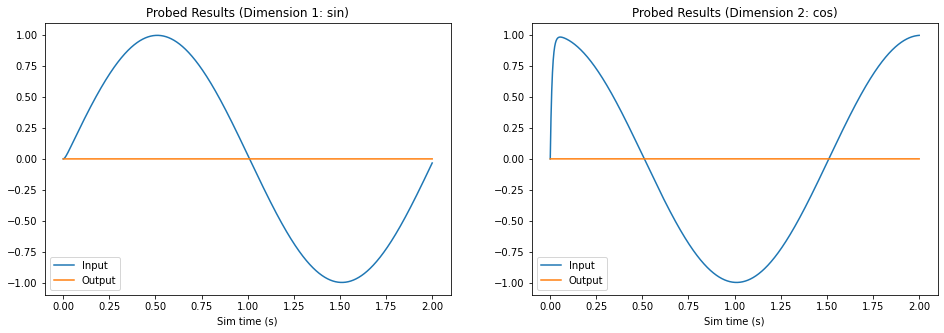
Notice that the output for both dimensions is zero, as expected.
Step 7: Set Weights and Test
Now, we will configure our FPGA ensemble to use the neuron parameters generated in Step 3. In order to demonstrate the correct behaviour of the network, a new Nengo simulation is created and run.
[8]:
with model:
    # Explicitly set ensemble attributes
    fpga_ens.ensemble.bias = bias
    fpga_ens.ensemble.encoders = encoders
    fpga_ens.ensemble.gain = gain

    # To set the decoders, we need to use nengo.NoSolver
    # to tell the builder we will provide out own decoders
    # (you can also set "weights" here instead,
    # see nengo.solvers.NoSolver for more info)
    fpga_ens.connection.solver = NoSolver(decoders.T)  # Transposed

with nengo_fpga.Simulator(model) as sim:
    sim.run(2)  # Run for 2 seconds
[9]:
plt.figure(figsize=(16, 5))
plt.subplot(1, 2, 1)
plt.title("Probed Results (Dimension 1: sin)")
plt.plot(sim.trange(), sim.data[input_p][:, 0])
plt.plot(sim.trange(), sim.data[output_p][:, 0])
plt.legend(("Input", "Output"), loc='lower left')
plt.xlabel("Sim time (s)")

plt.subplot(1, 2, 2)
plt.title("Probed Results (Dimension 2: cos)")
plt.plot(sim.trange(), sim.data[input_p][:, 1])
plt.plot(sim.trange(), sim.data[output_p][:, 1])
plt.legend(("Input", "Output"), loc='lower left')
plt.xlabel("Sim time (s)");
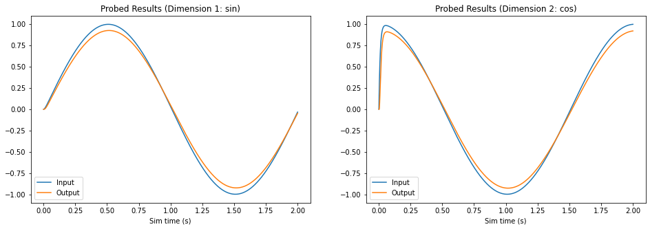
As the graphs above illustrate, now that the we’ve set neuron parameters to those we generated, the FPGA ensemble behaves like a communication channel and successfully reproduces the sine and cosine signals.